lgerold
Active Member
Hello!
We decided to build a skimmer similar to Snailman's 4" counter-current protein skimmer. You can see his plans at: http://www.hawkfish.org/snailman/diy4inskimmer.htm
Hubby, Mike, and I had some problems with the design, mostly with the fact that he uses glue to attach the body to the input and output PVCs, rather than actual fittings. We could just imagine one of our kids cranking on the skimmner, and causing a leak, so we designed our skimmer to use actual fittings whenever possible. It probably cost an extra 30 bucks, but the peace of mind is worth every penny. The total cost for this skimmer was about $85, without air pump or water pump.
I'll draw up some plans in the next day or two. These are photos of the skimmer, which I'll try to describe.
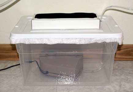
First, the entire system, set up in our mudroom, which happens to share the wall just behind the aquarium in the living room.
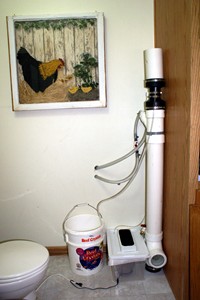
Next, a shot of just the skimmer. Overall, without the collection cup, the total height of the skimmer is about 5'.
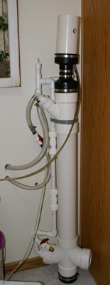
Now, a close-ups of the base of the skimmer.
You might wonder why in the world we used this odd fitting. The fitting was installed upside down by accident, but we think that the accident was good, because this way, it prevents air from building up in the fitting.
On the left side, the 4" PVC is reduced to 3/4" PVC, all with solid fittings, rather than by using glue. This is where the water flows OUT of the skimmer. Water travels out the left side of the fitting, up, and back to the sump. You can see that we have also installed a drain which we can use to easily drain the skimmer if necessary. On the vertical section of 3/4" PVC, we have installed a coupler (actually two) that is used to raise or lower the height of the water in the skimmer. The height of the water in the skimmer is controlled by the height of the top of this exit tube. From trial and error, we figured out that the top of this exit tube should be approximately at the height of the body of the skimmer. The coupler allows you to adjust this height by about 3".
Below is a tight close-up of the transional fittings from the 4" PVC fitting, to the 3/4" PVC fitting.
And, we wanted to install a window to view the airstone in use, so we could monitor its condition, and alter the amount of airflow. The window is on the right side of the fitting, and is shown below.
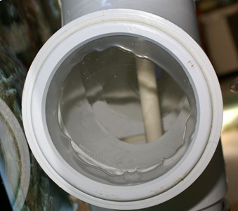
First, a picture showing the window. We simply cut a hole in the PVC cap, and used Marine Goop to glue a sheet of acrylic to the PVC. This is the only glued item, and because this secion is not under any stress, it should never fail.
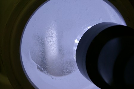
Below is the window in use. It's not at all necessary to use a flashlight as long as the light is on in the room.
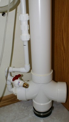
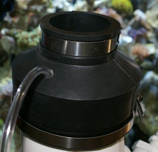
Now, moving to the top of the skimmer, here's a shot of the top half of the skimmer.
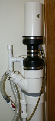
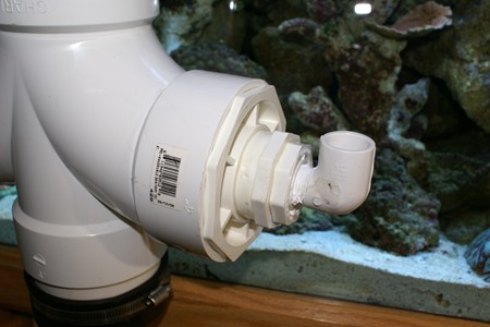
At the top of the skimmer, you see a Y shaped fitting. This section reduces the 4" body, to a 2" Y, and down to a 1/2" barbed fitting for the hose to the Mag 3 in the sump. Below is a tight close-up of that junction:
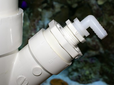
Remember one thing - the diameter of the line INTO the skimmer must be smaller than the diameter of the line OUT OF the skimmer, to prevent a flood. In our case, we used 1/2" flexible tubing INTO the skimmer, and 3/4" PVC and flexible tubing out of the skimmer.
Behind the input fitting, you can see the top of the 3/4" PVC line used to control the height of the water in the skimmer. We used a T fitting in the 3/4" line - the top side of the T leads to a cap with a small hole to prevent a siphon from developing. The bottom end of the T leads to a fitting taking you from 3/4" PVC to a 3/4" barb. Then, 3/4" flex tubing runs back to the sump.
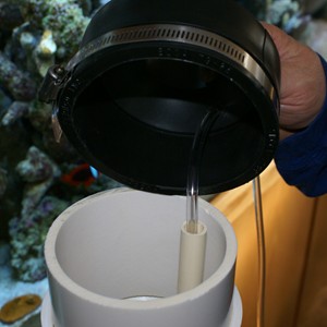
At the top of the skimmer body, we used two flexible rubber reducing couplings, one for the top of the body, and the second for the base of the collection chamber. A short 2" diameter piece of PVC runs from the bottom rubber coupling to the top rubber coupling, and 1" beyond the bottom of the coupling, to create a reservoir for skimmate. The collection chamber is simply a piece of 4" tubing. The bubbles go from the main body of the skimmer, up the 2" PVC, into the collection chamber. We drilled a hole through the rubber bottom of the collection chamber, and inserted a 3/8" barbed connector. One end of the connector goes into the rubber coupling, and the other goes to a piece of 3/8" flexible hose which leads to a 5 gallon bucket.
An airline hose runs from the airpump, through a tight hole drilled into the rubber reducer at the top of the skimmer body, through a 1/2" PVC tube, to the basswood "airstone" at the bottom of the skimmer. We used the 1/2" PVC just to keep the airstone at the bottom of the skimmer. Without it, the airstone would just float to the top.
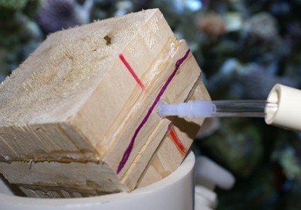
We built our own "airstone" out of a black of basswood. We cut square slabs of basswood, 2 1/2" square, 5/8" thick. Two of the pieces were cut across the grain, the third was cut with the grain. We soaked the three pieces overnight in freshwater. We then drilled a 2" hole in the center of the piece that was cut with the grain. We then made a sandwich of the three pieces, with the piece with the hole in the center. We used medium viscosity cyano glue to glue each piece of the sandwich together, and used thick viscosity glue (and accelerator) to caulk each of the joints. This glue can be purchased from hobby shops that cater to model airplanes. We drilled a hole the size of an airline connector, thorough the end of the center piece of basswood, into the hole in the sandwich. The air passes through the tube, into the center of the basswood block, and out through the pores of the stone. It was really simple! Only one stone is necessary, since the basswood creates a huge amount of very fine bubbles. It's supposed to be better than commercially produced stones. Below in the picture, the lines show the direction of the grain of the wood.
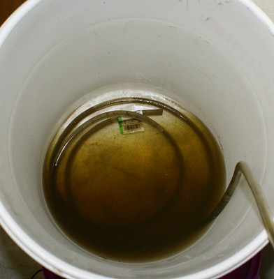
Below, is 36 hours of collection. It's working great!
We decided to build a skimmer similar to Snailman's 4" counter-current protein skimmer. You can see his plans at: http://www.hawkfish.org/snailman/diy4inskimmer.htm
Hubby, Mike, and I had some problems with the design, mostly with the fact that he uses glue to attach the body to the input and output PVCs, rather than actual fittings. We could just imagine one of our kids cranking on the skimmner, and causing a leak, so we designed our skimmer to use actual fittings whenever possible. It probably cost an extra 30 bucks, but the peace of mind is worth every penny. The total cost for this skimmer was about $85, without air pump or water pump.
I'll draw up some plans in the next day or two. These are photos of the skimmer, which I'll try to describe.
First, the entire system, set up in our mudroom, which happens to share the wall just behind the aquarium in the living room.
Next, a shot of just the skimmer. Overall, without the collection cup, the total height of the skimmer is about 5'.
Now, a close-ups of the base of the skimmer.
You might wonder why in the world we used this odd fitting. The fitting was installed upside down by accident, but we think that the accident was good, because this way, it prevents air from building up in the fitting.
On the left side, the 4" PVC is reduced to 3/4" PVC, all with solid fittings, rather than by using glue. This is where the water flows OUT of the skimmer. Water travels out the left side of the fitting, up, and back to the sump. You can see that we have also installed a drain which we can use to easily drain the skimmer if necessary. On the vertical section of 3/4" PVC, we have installed a coupler (actually two) that is used to raise or lower the height of the water in the skimmer. The height of the water in the skimmer is controlled by the height of the top of this exit tube. From trial and error, we figured out that the top of this exit tube should be approximately at the height of the body of the skimmer. The coupler allows you to adjust this height by about 3".
Below is a tight close-up of the transional fittings from the 4" PVC fitting, to the 3/4" PVC fitting.
And, we wanted to install a window to view the airstone in use, so we could monitor its condition, and alter the amount of airflow. The window is on the right side of the fitting, and is shown below.
First, a picture showing the window. We simply cut a hole in the PVC cap, and used Marine Goop to glue a sheet of acrylic to the PVC. This is the only glued item, and because this secion is not under any stress, it should never fail.
Below is the window in use. It's not at all necessary to use a flashlight as long as the light is on in the room.
Now, moving to the top of the skimmer, here's a shot of the top half of the skimmer.
At the top of the skimmer, you see a Y shaped fitting. This section reduces the 4" body, to a 2" Y, and down to a 1/2" barbed fitting for the hose to the Mag 3 in the sump. Below is a tight close-up of that junction:
Remember one thing - the diameter of the line INTO the skimmer must be smaller than the diameter of the line OUT OF the skimmer, to prevent a flood. In our case, we used 1/2" flexible tubing INTO the skimmer, and 3/4" PVC and flexible tubing out of the skimmer.
Behind the input fitting, you can see the top of the 3/4" PVC line used to control the height of the water in the skimmer. We used a T fitting in the 3/4" line - the top side of the T leads to a cap with a small hole to prevent a siphon from developing. The bottom end of the T leads to a fitting taking you from 3/4" PVC to a 3/4" barb. Then, 3/4" flex tubing runs back to the sump.
At the top of the skimmer body, we used two flexible rubber reducing couplings, one for the top of the body, and the second for the base of the collection chamber. A short 2" diameter piece of PVC runs from the bottom rubber coupling to the top rubber coupling, and 1" beyond the bottom of the coupling, to create a reservoir for skimmate. The collection chamber is simply a piece of 4" tubing. The bubbles go from the main body of the skimmer, up the 2" PVC, into the collection chamber. We drilled a hole through the rubber bottom of the collection chamber, and inserted a 3/8" barbed connector. One end of the connector goes into the rubber coupling, and the other goes to a piece of 3/8" flexible hose which leads to a 5 gallon bucket.
An airline hose runs from the airpump, through a tight hole drilled into the rubber reducer at the top of the skimmer body, through a 1/2" PVC tube, to the basswood "airstone" at the bottom of the skimmer. We used the 1/2" PVC just to keep the airstone at the bottom of the skimmer. Without it, the airstone would just float to the top.
We built our own "airstone" out of a black of basswood. We cut square slabs of basswood, 2 1/2" square, 5/8" thick. Two of the pieces were cut across the grain, the third was cut with the grain. We soaked the three pieces overnight in freshwater. We then drilled a 2" hole in the center of the piece that was cut with the grain. We then made a sandwich of the three pieces, with the piece with the hole in the center. We used medium viscosity cyano glue to glue each piece of the sandwich together, and used thick viscosity glue (and accelerator) to caulk each of the joints. This glue can be purchased from hobby shops that cater to model airplanes. We drilled a hole the size of an airline connector, thorough the end of the center piece of basswood, into the hole in the sandwich. The air passes through the tube, into the center of the basswood block, and out through the pores of the stone. It was really simple! Only one stone is necessary, since the basswood creates a huge amount of very fine bubbles. It's supposed to be better than commercially produced stones. Below in the picture, the lines show the direction of the grain of the wood.
Below, is 36 hours of collection. It's working great!

")