You are using an out of date browser. It may not display this or other websites correctly.
You should upgrade or use an alternative browser.
You should upgrade or use an alternative browser.
DIY LED questions
- Thread starter swimmer4uus
- Start date
swimmer4uus
Member
are you getting the 1.25v because that LED uses 1.25v? and if you run more then 1 led in series then does that change the formula?
No, it's just the formula you have to use with this chip. The LEDs themselves drop ~3.2V. Also, this driver will drop 3V. Compaired to drivers off the self that drop only like .2 volts, it's not very efficient. BUT, more LEDs powered, the more efficient it gets because the LEDs drop more voltage.
Hope all this is coming across ok because it's a little hard to explain when you're not in person.
swimmer4uus
Member
your doing a great job explaining it. i know its kinda hard to type an explaination that can be long as hell but thanks i am getting it for the most part.
so each driver is limited to about 5 LEDs then? somthing to do with the rating of the chip?
Nah, the LM317 can take up to roughly 10 3W LEDs. But yes, the idea is correct. The chip can only go up to roughly 37 volts and 1.5 amps. So, 37/3.2 is 11...something. Which is roughly 10 LEDs. Any driver will have this limitation though. It just depends on the chip being used. Most don't go over 40 volts.
swimmer4uus
Member
i thought most store bought drivers could only handle 6 LEDs. or maybe its the LED's cant handle that much current passing through them. there has got to be a reason why eveyone else only does 6 per diver. do you plan to run 10 off each driver?
It depends on the driver. In other cases (and with the new one I'm prototyping) the chips being used, and the configurations they are in, limit the amount of LEDs you can do. The LM317 isn't really a current driver, but uses voltage to indirrectly regulate the current.
The reason why off the shelf drivers are limited to so many LEDs is the way they are designed. There are two main designs out there right now, boost, and buck. Buckpucks are in the buck configuration. Boost topology is when your power supply is giving you a certain voltage, your driver will then UP that voltage making you able to drive more LEDs. Buck is the opposite. Your power supply gives you a certain voltage, and the driver chops it down.
Now, LEDs are current regulated, meaning the lower the current, the less brighter it will be. BUT your voltage determines how many you can run in a string. 48 Volts at 1000mA can run 18 3w LEDs. 24 Volts at 1000mA can only run 7. The reason people suggest 6 is to give yourself a little bit of room to play with, just in case your power supply isn't running right at 24V.
I WAS, and the key is was, going to run 5 LEDs in a string off of the LM317. Now that I've read some more, I can make a buck topology driver, for about the same cost, and have more bells and whistles. At the moment, I'm waiting on some parts to come in before I can get my first prototype running. Total cost for 10 drivers worth is 50 bucks, and a little heavy duty reading. Unfortunatly it won't be as efficient as if I would have ran 6 LEDs on the string as the LEDs where already mounted onto my heatsink, and it's going to be easier if I just stick to my current configuration.
swimmer4uus
Member
so your in the middle of setting up a new kind of driver? you are doing it different then you showed in the last few posts? it will be intresting to see how that turns out. keep us posted.
Yes. Now only if the parts would arrive in the mail!!
swimmer4uus
Member
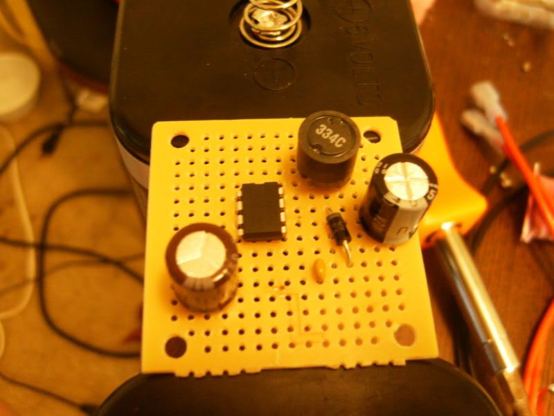
So I'm starting my NCP3066 based driver. I'm reading the circuit, and putting parts in place. Pretty simple so far but ran into some questions. Getting them answered and then will actually start soldering.
swimmer4uus
Member
how much do the parts cost to make this? i think a standard driver cost $15 and a dimable driver cost about $20. + shipping.
if this is cheap then i may ask you to go into detail of this too.
hope im not bugging you, but the people want to know.
Here's cost from my purchase orders not including shipping. I accidentally forgot the Inductors so made a 2nd order. AKA 2 shipping charges.
 (Numbers in front are quantities)
First PO
10 Inductors Digikey Pt. #811-2103-ND Unit Price $.813 Total $8.13
Second PO
10 Capacitors Digikey Pt. #565-1707-ND Unit Price $.299 Total $2.99
10 Capacitors Digikey Pt. #BC1074CT-ND Unit Price $.07 Total $0.70
10 Schottky Digikey Pt. #1N5819GOS-ND Un Price $.395 Total $3.95
10 Capacitors Digikey Pt. #493-1342-ND Unit Price $.312 Total $3.12
Total without shipping $18.89
FOR 10 DRIVERS!
Let's compair total numbers (these are for 10 drivers total)
DIY with dimming: $18.89
Buckpucks Non dimming: $149.90
Buckpucks with dimming: $159.80
Interesting
swimmer4uus
Member
im sold. when you going to do a test of thuis new driver? how do you adjust the light with that. i never could figure out what and how a "pot" works.
So the new driver is targeted for 750 mA max current. This driver is a pulse-width modulation device. I'll leave that for you to go google, but basically it turns full power on and off so fast, that we cant see that overall effect, other than the lights being dimmer. So, that means it's a little more tricky to find a dimmable circuit for it, BUT, also means this can be connected to a microcontroller (aka Arduino), that we can then program to do some amazing stuff. For now I'm going to make a dimmer circuit that will provide the drivers the right signal for analog dimming.
I've got to wait on my last 2 resistors to come in before I can finish the driver, and slap it on some LEDs.
A potentiometer is just a resistor, that you can adjust. You turn the nob, the resistor value changes. I think wikipedia has a good writeup on it actually.
swimmer4uus
Member
do you know of any good web sites or books or something to help me understand ciruits better? i look at the diagrams for these DIY drivers and get lost by all the little symbols. i think if i understand those better then i can see how the thing works better.
I'm not too sure on any books. I'm an engineering major and one of the requirements is to take a basic circuits class. Now, the diagrams are complicated even to me though. For this driver, I'm pretty much just soldering exactly like the diagram. There is a trick though on getting polarity correct, because in the real world, we aren't dealing with perfect components. The hardest thing for me was taking it from paper, and putting it into use in the real world. You can't always find those wierd values, so must compromise. It's fun to learn, but for the sake of this particular driver, I'd "hold your hand" through the process if you wanted to take a stab at it yourself.
Feel free to make use of this thread. I'll be glad to answer questions to the best of my knowledge, but if it's more complicated, I'll have to refer to others myself.
zigginit
Member
thanks for the help. i sure am learning a lot. i found this web site and its helping. its an online text book about circuits. All About Circuits : Free Electric Circuits Textbooks
swimmer4uus
Member
Yeah, reading and trying to figure this stuff out on your own is not easy. There's a lot of reading, and not saying it can't be done, but good thing we are doing it for a fish tank, other than that I probably wouldn't be doing it myself.
Boomer
Reef Sanctuary's Mr. Wizard
swimmer4uus
Just wondering ever think of using Cree 4-Core/Chip LED's like XR-E or MC-E.
1 XR = ~100 l DL ( Daylight) @ 350 mV and can be driven to 1,000 mV
1 MC = ~ 400 l DL @ 350 mV and can be driven to 700 mV
Yes they would have to very heat-sinked and fanned.
Just wondering ever think of using Cree 4-Core/Chip LED's like XR-E or MC-E.
1 XR = ~100 l DL ( Daylight) @ 350 mV and can be driven to 1,000 mV
1 MC = ~ 400 l DL @ 350 mV and can be driven to 700 mV
Yes they would have to very heat-sinked and fanned.