swimmer4uus
Member
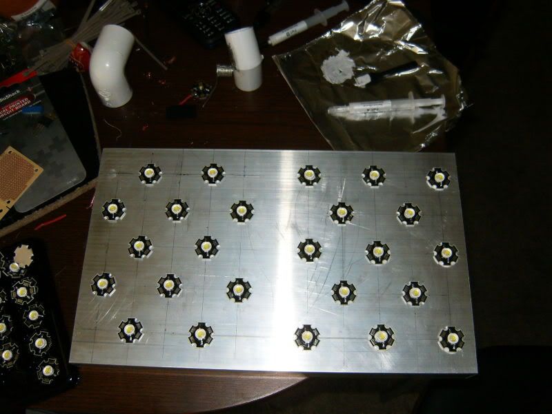
60 whites!?!? how big is this fixture gonna be?
48"
I saw another build on nano reef that the guy has 2 20" long heat sinks. Pretty impressive
60 whites!?!? how big is this fixture gonna be?
 arty:
arty: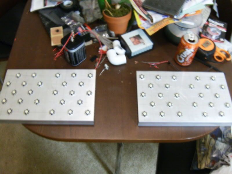
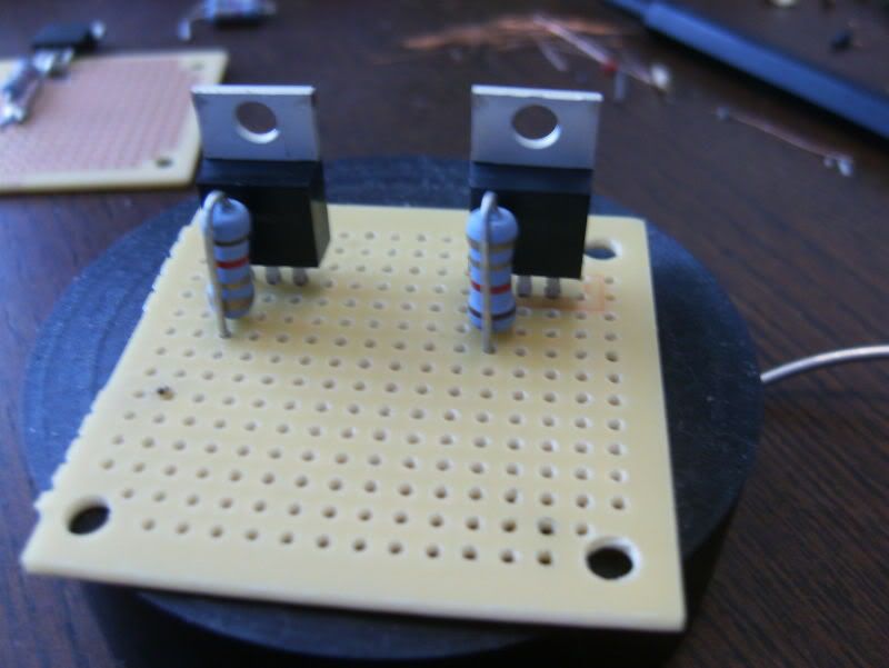
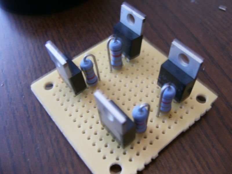
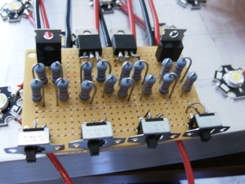
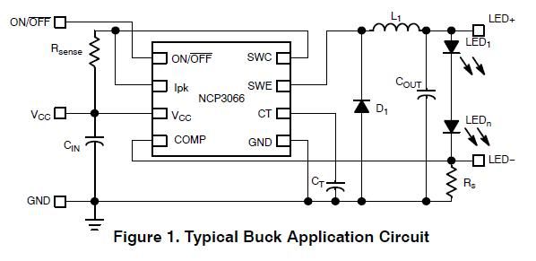
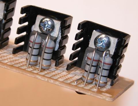
so am i looking at 4 drivers on one project board? why are the 2 in the middle laying down? i like the way that you did this and would like to know a really dumbed down explanation of what im looking at. is that all thats in a driver 4 resisters and whatever that black thing is? (what is it). nice build so far.
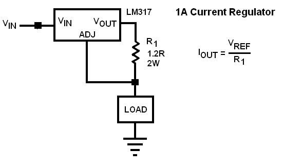
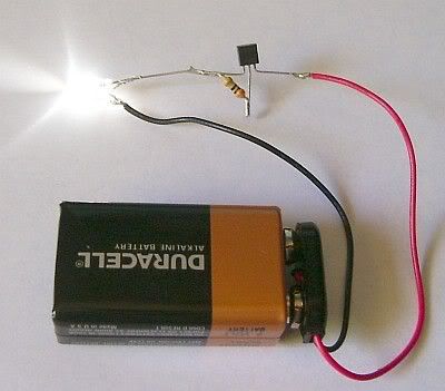
wow thanks for the great write up on this. it sure dose seem like you know a thing or two about doing electrical work. wish i could learn more about it. what is the ADJ on the first pic mean and why dose it jump in line past the resistor? dose the negitave end just go from LED to power supply again?
so i see your calculations above and have a question. so you want to drive at 750ma so you used 0.75A. the 1.25 was the resistor you used. what does the 1.777 mean? what roll does that number have in this? isnt 1.777 Ohms more then the 1.25 resistor you put on it? is the differance between the 1.25 and the 1.777 mean something?