Jimbo_zzr6
Member
Any experienced sparkies on here need help with ballast wiring please.
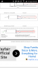
You need to read the diagrams and see what each pin does. Odds are the difference in the number of pins is because of a shared ground on the new ballast, as opposed to two discrete grounds on the OE ballast. But look to be sure!
As you can see the common connection between the red wires on the red sea max ballast is not on the new ballast. So when I would wire it up I would be left with the middle wire. The tridonic 2x39 wiring diagram doesn't state anything about a common connection!!You need to read the diagrams and see what each pin does. Odds are the difference in the number of pins is because of a shared ground on the new ballast, as opposed to two discrete grounds on the OE ballast. But look to be sure!
")
Cheers again Dave. All done now until you said that for some reason I was scared of changing the wiring incase I blew my rsm hood up. Lol just removed the continuous spur from the circuit and wired new bsllast in. Only difference now is that on the old ballast if 1 tube wasn't working the other still would. But on the new one if a tube goes both stop. Pretty simple really thanks again.When you get a ballast that shows a different wiring configuration compared with what you have, you change your wiring to match the new ballast. This way you know the new ballast will work. You may need to add or remove wires to make this happen. I have done this several times on other lighting fixtures when I was unable to obtain an exact ballast match.